

| Configuring CICS for Security | CICS Communications Using Microsoft SNA Server | |
This chapter describes how to set up and configure terminals and printers for the CICS Option component of Mainframe Express.
The user interface to CICS Option applications from the PC is through 3270 terminal emulators. The 3270 terminal emulators enable CICS Option to display CICS application input and output screens on the PC using 3270 data streams and to receive input from the PC.
When you start a 3270 terminal emulator, it is installed into a CICS Option region. The parameters that describe the terminal are determined either by a set of default rules, or by an autoinstall control program (ACP). CICS Option uses autoinstall to install terminals; if you want to configure or control the way autoinstall behaves, you can supply an ACP.
This chapter describes the default installation parameters and the steps needed to implement user autoinstall on a region, as well as the details of the ACP interface.
You can also connect 3270 terminal emulators running on other multi-tasking Windows NT machines to CICS Option over a network.
CICS Option does not require a Terminal Control Table entry to be defined for each terminal. Instead, it creates an entry dynamically each time a user starts a 3270 terminal emulator.
When you start a terminal emulator, it passes a set of parameters to the autoinstall program. These can all be set from the Mainframe Express IDE, except for the screen size, which the emulator picks up automatically from its environment.
CICS Option then builds a Terminal Control Table entry from the parameters supplied in one of two ways:
Autoinstall provides you with greater flexibility in defining terminals, but requires some work to implement (see the section Implementing the Autoinstall Exit).
The resource definition file supplied with CICS Option contains a group, DFHTERM, which contains example 3270 terminal definitions. The supplied group contains the following definitions:
| Model | Model Name | Netname | Termid |
|---|---|---|---|
| 2 | MODMOD2 | NETMOD2 | MOD2 |
| 3 | MODMOD3 | NETMOD3 | MOD3 |
| 4 | MODMOD4 | NETMOD4 | MOD4 |
| 5 | MODMOD5 | NETMOD5 | MOD5 |
If you want to use one of these definitions, you must include the group DFHTERM in the startup list for the project, as follows:
To select one of these terminal definitions, you use the Configure Default Terminal dialog; either:
or:
If you are using a multi-tasking region and would like multiple 3270 terminals connected to the same region to use the same terminal definition then you must select Model in Based on and specify the model name you require from the table above in Name. The termid and netname will be assigned automatically during auto-install.
If you require a particular termid or netname or have no requirement to share the terminal definition then you should select Netname in Based on and specify the netname you require from the table above in Name. The termid and netname you specified will be assigned during auto-install. If the netname is already in use then the the auto-install process will fail.
When a 3270 terminal emulator starts, it passes a set of parameters to CICS Option. These are either used to install the terminal directly, or passed to the autoinstall process.
The parameters passed to autoinstall are:
The supplied autoinstall exit DFHZATDX selects the best model definition match based on screen size. If you write your own autoinstall program you can select the model and change other parameters such as the terminal ID.
Note: DFHZATDX is not a supplied program. It is a special name that drives the auto-installation behavior.
To implement autoinstall in a region you can use the supplied autoinstall exit program DFHZATDX or you can specify your own autoinstall control program (ACP).
To use your own ACP you must:
The interface to ACP is fully defined below. Put the executable file for the program on the program path. The Autoinstall Processing section describes the flow of information between the ACP and a CICS Option region.
Information on updating the SIT is available in the online help; click Help Topics on the Mainframe Express Help menu, then on the Contents tab click CICS Option, Defining Resources, How to View and change the SIT. You should be aware that the autoinstall exit interface is designed to be an ASCII interface. The autoinstall exit you specify in the AI field in the SIT must be a compiled ASCII program.
You should write an ACP that is supplied with:
The control program returns:
The ACP has the following call interface:
ENTRY ai-prog-name USING a-string pointer-1 pointer-2
       pointer-3 pointer-4
where:
| ai-prog-name | is the program name entered in the AI Exit field of the SIT. |
The remaining parameters are part of DFHCOMMAREA as follows:
01  DFHCOMMAREA
    03 a-string     PIC X(4).
    03 pointer-1    POINTER.        pointing to Net-Info.
    03 pointer-2    POINTER.        pointing to Model-table.
    03 pointer-3    POINTER.        pointing to TCT-Info.
    03 pointer-4    POINTER.        pointing to Term-Info.
| a-string | contains x'F0' in the first byte. If the autoinstall exit is to reject the install attempt, the ACP should not alter this value. If the autoinstall exit is to accept the install attempt, the ACP should set a-string to LOW-VALUES. |
| pointer-n | is defined further in the following sections. |
This data format and those for pointer-1, pointer-2, pointer-3, and pointer-4 are supplied in copybook dfhcwai.cpy.
Pointer-1 points to memory block 1.
Memory block 1 is passed to the ACP with data in the following format:
01  Net-info.
    03 name-length      PIC X       COMP-X.
    03 netname          PIC X(8).
where:
name-length |
Contains the length of the netname field. This field is padded with spaces to eight characters. |
netname |
Contains the netname. |
Pointer-2 points to memory block 2.
Memory block 2 is passed to the ACP containing the list of suitable autoinstall models for the physical screen.
01  Model-table.
    03 table-name-count PIC X   COMP-X.
    03 autinst-name-1       PIC X(8).
        . . .
You can include
between 1 and 100 entries of autinst-name-n,
depending on table-name-count.
where:
table-name-count |
Number of entries in the table |
autinst-name-n |
Autoinstall model name. |
The memory block contains table-name-count autoinstall
entries.
Pointer-3 points to memory block 3. The ACP uses memory block 3 to return information enabling CICS Option to create a TCT entry and log the terminal on to the system.
01 TCT-Info.
    03 autinstname          PIC X(8).
    03 terminal-id          PIC X(4).
    03 printer-id           PIC X(4).
    03 altprinter-id        PIC X(4).
    03 status-byte          PIC X(1).
where:
autinstname |
The name of the autoinstall model to be used to create the terminal. |
terminal-id |
The ID with which CICS Option registers the terminal. If the ID is set to LOW-VALUES, CICS Option assigns an ID automatically. CICS Option terminal ids are assigned from A0000, B0000... to Z9999. |
printer-id |
Printer to assign to the terminal. If set to LOW-VALUES, CICS Option assigns the printer defined for the autoinstall model. |
altprinter-id |
Printer to assign to the terminal. If set to LOW-VALUES, CICS Option assigns the alternate printer defined for the autoinstall model. |
status-byte |
Set this byte to LOW-VALUES to register the terminal. If set to any other value, CICS Option aborts terminal registration. |
Pointer-4 points to memory block 4.
Memory block 4 contains data in the following format:
01 Term-Info.
    03 term-info-length PIC X   COMP-X.
    03 height               PIC X   COMP-X.
    03 width                PIC X   COMP-X.
    03 uctran-setting       PIC X.
where:
term-info-length |
Length of following control block. In this release, always contains 3. |
height |
Height of physical display in rows. |
width |
Width of physical display in columns. |
uctran-setting |
Contains U if uppercase translation was enabled on the Configure Default 3270 Terminal dialog box. |
This section explains the process and information flows when a user starts a 3270 terminal emulator from the Mainframe Express IDE.
Figure 9-1 illustrates the steps in the autoinstall process.
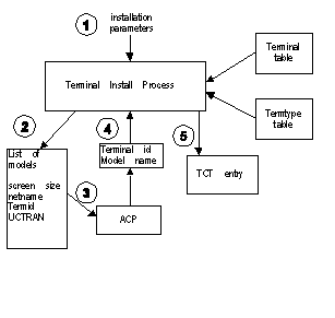
Figure 9-1: The autoinstall process
The ACP also supplies the name of a printer and alternate printer to be associated with the terminal.
A terminal model enables you to define a terminal more fully than the default parameters supplied at terminal startup (see the section Terminal Installation Parameters earlier in this chapter). A terminal model can also override some, but not all, of the defaults supplied at startup.
The steps to define a terminal model are outlined below. You must use the character interface to resource definition (click Resource Definition from CICS on the Tools menu) to define the terminal and typeterm entries. Within resource definition you can get help information on each field by pressing Alt+F1=help.
Many different models can refer to the same typeterm entry.
A terminal model can override some, but not all, of the parameters defined in the section Terminal Installation Parameters.
The list below shows the scope of what a terminal model can do:
| Parameter
|
Model
|
|---|---|
| Screen size | Can define screen size as the same, smaller, or up to one line longer (see the section Screen Sizes). |
| Uppercase translation | Can enable uppercase translation. |
| Netname | Cannot change. |
| Initial transaction ID | Can supply a transaction ID, but cannot override one set on the Configure Default 3270 Terminal dialog box. |
You can define a TCTUA in several ways. In each case you must define the terminal and typeterm entries using the character interface to resource definition - click CICS on the Tools menu of the IDE, then click Resource Definition. From the main menu, press F7, enter the group name, press Enter. From this menu either press F9 followed by F2 to define the terminal model, or press F10 to define the typeterm.
You must then define a typeterm and set the terminal type to the name you supplied in the Term Type field of the terminal definition (TCTUATYP in the example above). You should also set the User Area Size field (a value from 1 to 255). You must also enter Y in the Uppercase Translation field if you require uppercase translation.
Either:
Start the terminal specifying NETTCTUA as the netname and it will use this terminal definition. (This can only be used for one terminal in a multi-tasking system so is only recommended for the single-tasking system.)
or:
Start the terminal specifying MODTCTUA as the model name and it will use a terminal definition modelled on the TCTUATYP typeterm.
If the Model is specified as "Y" then a netname is required. However if a model is set to "O" - Model only, then no netname is required.
CICS Option supports displays of up to 132 columns by 31 lines (a maximum of 4096 characters). The standard screen sizes are:
| MOD2 | 24 x 80 | |
| MOD3 | 32 x 80 | |
| MOD4 | 43 x 80 | |
| MOD5 | 27 x 132 |
Whenever you start a 3270 terminal emulator, it passes the physical screen size to the autoinstall process, deducting one line from the length to allow space for the status line.
The autoinstall process treats any screen size defined in the typeterm as compatible if it is no more than one line longer than the physical screen size as defined by the terminal emulator program. That is, there are enough lines for the data, but no separate line for the 3270 status line.
The terminal emulator handles the status line in different ways, depending on whether the physical screen can display it on its own separate line or not. This is covered in the next section.
3270 terminal emulators have four status line display modes, through which the end-user can cycle by pressing Alt-T:
| ON | Status line permanently displayed. Set whenever the physical screen is physically large enough. |
| OFF | Status line permanently disabled. Terminal user selectable option. |
| X-SYSTEM | Status line displayed briefly over bottom line of data whenever there is a system status change, message or INHIBIT INPUT. Set whenever the screen is not physically large enough. |
| Hot-key | The terminal user can toggle the status line on or off by pressing Alt-S. When displayed, the status line overlays the bottom line of data; toggling it off restores the data line. Terminal user selectable option. |
Light pen support is provided through a mouse simulation of the light pen facility.
If you do not have your own autoinstall exit, use the character interface to resource definition (click Resource Definition from CICS on the Tools menu) and:
| Model | Y |
| Auto Install Model Name | MODLPEN |
| Net name | NETLPEN |
| Term Type | LPENTYPE |
| Inservice | Y |
| Connection Type | TERMINAL |
If you have your own autoinstall exit you should ensure that light pen is specified in the terminal model you use.
Mouse button 1 (left button) positions the cursor at the indicated character
Mouse button 2 (right button) behaves as follows:
Double clicking mouse button 1 is equivalent to one click of mouse button 2.
You can use a printer device for 3270 printer support. Printer support is handled by 3270 printer emulators, which interpret the 3270 printer data stream and send it to a system printer.
To start a printer emulator in a CICS Option multi-tasking region, you must enable printer support. To do this update the following fields in the SIT using the character interface to resource definition (click Resource Definition from CICS on the Tools menu):
| Field
|
Contents
|
|---|---|
| Printer Support | Y |
| Printer Destination | Device name for printed output |
A CICS Option multi-tasking region starts a printer emulator for each entry in the terminal table which is:
The netname defined in the terminal table must be unique to the region. The terminal ID for the printer is taken from the terminal definition.
To avoid conflicts with automatically assigned netnames (see the section Terminal Installation Parameters), you should assign netnames to printers counting downwards: PRNZ999, PRNY999 ... PRNA000.
Copyright © 1999 MERANT International Limited. All rights reserved.
This document and the proprietary marks and names
used herein are protected by international law.
| Configuring CICS for Security | CICS Communications Using Microsoft SNA Server | |