

 | Setting Up Projects | Information Browsers |  |
Revolve tools provide powerful insights into how your source code systems function. These tools include:
Access Tools by selecting the desired tool from the Tools menu or from the speed menu (right-click mouse).
To enable the Shell tool, select REQL Shell on the User
Options dialog. The Shell tool permits access to the source code
with a simulated command line interface. Commands and functions can be
applied to projects for advanced analyses. The names and paths of selected
items appear at the bottom of the Shell and at the bottom of the
Revolve desktop. When the Assign Scope... button
 is clicked the scope of the analysis is set to the
component which contains the selected item.

The Metrics tool calculates four statistical measures of complexity:

The Metrics tool is set to Halstead by default. To change the Metrics default mode go to Utilities/Options/Tools/Metrics menu. A Metrics Options dialog will be displayed featuring a pull down list box where the default mode can be changed.
The Halstead metric mode, invoked by pressing its button
 , uses four numbers to
calculate the estimated length of each program. These numbers are the total
number of operator occurrences (N1), the total number of operand occurrences
(N2), the number of distinct operators (n1), and the number of distinct
operands (n2). With these numbers, Halstead estimates the program length to
be:
N = N1 + N2
The volume to be:
V = N log2 (n1 + n2)
The McCabe metric mode, invoked by pressing its button
 , calculates the cyclomatic,
extended, and essential complexity of each paragraph and program. These
numbers represent the number of logical paths through the source code.
The McClure metric mode, invoked by pressing its button
 , calculates complexity for
each paragraph and program as the number of conditionals plus the number of
unique operands used in the conditionals.
Statistics metrics mode, invoked by pressing its button
 , displays the number of
lines and statements in each paragraph and program.
The Sort button  displays
a sort dialog. With each of the Metrics modes, Revolve can sort information
by different fields and allow the user to organize the display of information
in the Metrics information window.
 invokes the Modification Driver dialog
which allows user-defined text to be automatically entered into the source
code of selected items. This functionality is especially useful for the
implementation of source code changes.
See also For details on the functionality refer to Modification Driver .
Revolve's implementation of Function Point Analysis is based on the International Function Point Users Group's (IFPUG's) 3.4 function point analysis definition.
When the Function Point Analysis tool is invoked, a Choose dialog is displayed. The analysis is performed on the entire project or on information that has been isolated to a subproject. If the analysis should be performed on the entire project select NONE. If the analysis should be performed on a defined subproject select it from the list and click OK.
Note: It is recommended that the Complete Project dialog box be used to provide Revolve with any missing information before the Function Point Analysis tool is opened. Refer to Complete Project.
Use the Function Point Analysis tool to measure the complexity of your project. Function Point Analysis first identifies and organizes the system's business functions into five groups:
Note: Revolve classifies screen accesses as either inputs or outputs. Data files are classified as ILF (Internal Logical File) or EIF (External Interface File). The distinction is made in that ILF's are written to and EIF's are not.
Then each business function is classified and weighed by its level of complexity (low, average, or high). Finally, the numbers are totalled to establish the complexity of your project. The higher the total is the more complex the project is. The evaluation process can be viewed in the Function Point Analysis window.
The Options button  opens the Complexity Factors dialog box, where you define weighting
factors that adjust the parameters of the Function Point Analysis. A
numerical value is determined based on the designated weight of each function
where 0 represents no influence and 5 represents strong influence. The
defaults for this dialog can be changed with the Complexity Factors option
on the Utilities/Options/Tools/Function Point Analysis menu.
The Classifications button opens the File Types dialog box which allows for file types to be specifically identified. By selecting an item and clicking the specific button, elements can be designated as inquiries, inputs, outputs, ILF, or EIF. If an element is unused it can be tagged unused.
The Assign Scope... button  displays the
Subprojects dialog box and allows the Function Point Analysis
to be limited to a predefined subproject. To perform Function Point
Analysis on a subproject, select the subproject's name from the list and
click OK.
See also For information about creating subprojects, see Subprojects.
Revolve is a powerful application for system maintenance, due in large part to its advanced analysis and editing capabilities. You can examine entire systems for problems and find necessary changes with the tools and browsers included in Revolve. Then those changes can be implemented directly into the source code with the Integrated Editor. The editing capabilities make Revolve both efficient and dynamic; however, modifying and editing source code can threaten source code integrity because of the possibility of data impacts. Data impacts occur when data items refer or relate to one another in a project through moves, redefines, conditionals, arithmetic operations, group relations, parameter passing, copybooks, references to files, and references to screens. When one item is changed it can affect items all over the project. To guarantee integrity, Revolve includes the Impact Analysis tool to provide you with detailed information about data movement through source code and impacts that may occur between data items.
Note: It is recommended that the Complete Project dialog box be used to provide Revolve with any missing information before the Impact Analysis tool is opened. Refer to Complete Project.
Step 1: Define Starting Points
The first step in impact analysis is defining starting points. With the Impact Analysis tool you create a pool of data elements and reduce it to likely impact candidates. Revolve uses the candidates as starting points for impact tracing.
Impact Analysis for the Assembler Extension uses variables as starting points and traces through direct variable manipulation in MOVE statements.
 and set the
options you want. See Impact Options.
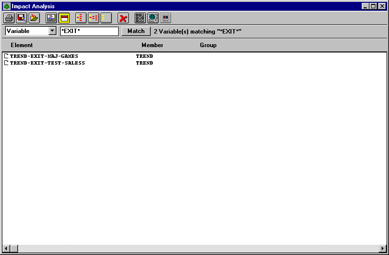
The Impact Analysis tool fills with project elements that match
the criteria you entered into the Match edit field and in the Impact
Options dialog. Now that you have a list of impact candidates, you can
cycle through the list while examining each element's source code in the Split
Screen Editor  . Remove those elements you find
which are not pertinent to an impact analysis with
  until you have a list of viable starting points for the impact trace.
Step 2: Impact Tracing
The next step is to perform an impact trace. During impact tracing Revolve
uses each candidate as a starting point in the source code for impacts with
other project elements. To initiate impact tracing, click
 . By default, the Impact Analysis tool
displays all results by Impact Group. You can change the Impact Analysis
display in the Display Mode dialog
  .
See Display Options.
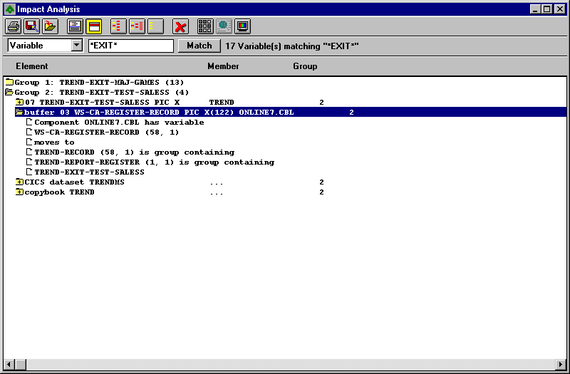
Expand the folders to view the chain of events that led to each impact.
The trace chain of events are displayed as leafs  . Each
leaf details a step in the data movement leading up to the impact of an item
with the impact candidate.
During impact tracing the Impact Analysis tool analyzes data for all project entities that are effected when the variable, BMS field, or MFS field is modified. Impacts are categorized into the following types:
Note: To view impacts by type select Type in Display Mode.
When Early Release Options is checked in the User Options dialog, the Duplicates button will appear on the Impact Analysis button bar. When this button is clicked or engaged, all logical matches of the type/name specified will be displayed. When this button is not engaged, or not visible, only one variable per physical definition will be displayed.
In Impact Options  you define how the
Impact Analysis tool traces impacts in your project.
| Select This:
|
To Trace Through:
|
|---|---|
|
Conditions: |
Comparisons; for example, less than, greater than. |
|
Literals: |
Literals and constants. |
|
Arithmetics: |
Arithmetic operations; for example, ADD, SUBTRACT, and COMPUTE. |
|
Redefines: |
Redefined memory space. |
|
Copybooks: |
Variables in copybooks through all copybook usage. |
|
Data Files: |
All usage of Data Files. |
|
Executables: |
Parameters through calls. |
|
Screens: |
BMS/MFS fields through all screen usage. |
|
Moves: |
Variables through move operations. |
You can Prune from Impact Options. Pruning allows you to cut unnecessary data out of the analysis results. Pruning options are described as follows:
The Impact Analysis tool gives you various modes in which to view
the results of an impact trace. Invoke the Display Mode dialog with
 .
.

| Select This:
|
To Do This:
|
|---|---|
| By Name: | Organize all impact items by name. |
| By Source Member: | List all impacts by their location in the project database. |
| By Program | Assemble the analysis results by the program through which the impact is logically defined. This option differs from the By Source Member option in that copybook-defined variables will appear in the folder for each program that includes the copybook. |
| By Type: | Arrange the results according to the type of the impact. Types are grouped by: Synonyms, Buffers, Files, Copybooks, Screen Fields, Literals, Screens, Global Variables, Executables. See Moving Through the Impact Trace. |
| By Impact Group: | Display impacts by grouping them according to the candidate. The top line in the folder represents the impact candidate. Each subsequent folder represents items that are effected if the candidate is modified. The number in parentheses beside the group number represents the number of impacts. If that number is one, there is only one occurrence and no additional impacts for the candidate. |
The Syntax Checker works in conjunction with Micro Focus COBOL Workbench to check syntax in programs. It is only available in the 32-bit version of Revolve and requires version 4.0 of Micro Focus COBOL Workbench.
Revolve expects the environment to be correctly configured to execute COBOL.EXE. If the appropriate environment variables are not configured, then you should start Revolve with the command line:
MFENV 32 <revolve directory>\REVOLVE\BIN\REVOLVE.EXE
Revolve uses the information in the database to set directives and environment variables for the checker. Those are augmented by the RVCHK.DIR file located in the \revolve\bin subdirectory. Additionally, if user specific directives are necessary, Revolve will look for C:\RVUSER.DIR. Any warnings or errors are displayed under the program folder.
The Load Selected button  initiates a
compile of the selected items in the Syntax Checker.
Options for the Syntax Checker can be modified in the Options
dialog, invoked with  . If the environmental
variable WBADVCFG is non-existent, undefined, or set to "no" then
the following dialog will be invoked.

The Use COMPOPT check box enables access to the Micro Focus Workbench Compopt tool.
If the environmental variable WBADVCFG is defined and set to "yes"
then the following dialog will be invoked when the Options button
 is clicked.
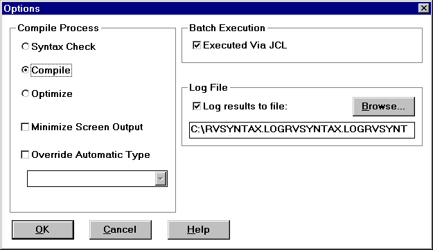
Syntax Checker Options are described as follows:
| Select This:
|
To Do This:
|
|---|---|
|
Syntax Check: |
Valid for COBOL and PSB. Syntax errors and warnings that were found during the compile are listed under the component in which they occurred. An .MSG file is generated for COBOL and an .ILS file is generated for PSB. |
|
Compile: |
Valid for COBOL, Assembler, DBD, PSB, MFS, and BMS. Syntax errors and warnings that were found during the compile are listed under the component in which they occurred. An .MSG file is generated for COBOL, Assembler, and BMS, and an .ILS file is generated for DBD, MFS, and PSB. |
|
Optimize: |
Valid for COBOL and Assembler. No output file is generated. |
|
Minimize Screen Output: |
Specifies that the above operations be performed without the graphical output. This option greatly improves performance. |
|
Override Automatic Type: |
Turns off/on Revolve's Automatic Typing functionality. Note that components sent to the Workbench as a wrong file type may return unpredictable results. If you select this option you must choose a file type from the pull-down list box. All components processed by the Workbench will be considered as files of the specified type. |
|
Batch Execution: |
Specifies which directive will specify the COBOL file handler during execution: JCL, the default CALLFH(EXTFH),or CALLFH(PROXFH). |
|
Log Results to File: |
Checkbox designates a log file of the checking procedure to be created in the specified directory. The Browse button opens a Get Log File Dir dialog, in which you can navigate to the desired location of the log file. |
The Scripts tool provides the user with access to scripts that automate specific tasks in Revolve.
The scripts are organized into the following categories:
When some scripts are initiated a Choose or Choose Components dialog appears in which you must choose the components or items that are to be included in the script's execution. The following section describes the available scripts.
Shows records used in I-O against batch files and the copybooks containing the record layouts. Records moved to or from I-O records are included in the record list.
Shows records used in I-O for CICS datasets and copybooks containing the record layouts. Records to which I-O records are moved are included in the record list for a dataset.
Shows files accessed by their procedure.
Shows files accessed by programs. Records displayed for program/file are records READ INTO or WRITTEN - REWRITTEN FROM, as well as the data record defined in the FD.
Shows procedures accessing files by file.
Shows programs accessing files by file.
Finds variables whose names are the same but whose PIC clauses define different types or sizes.
Counts the number of lines that are loaded for each component.
Counts logical and physical line numbers for all project members. It will generate four columns:
|
Module Name: |
Specifies the project module's name. |
|
Logical: |
Refers to the total number of lines in a member, including imported elements (copybooks, procs, etc.). |
|
Physical: |
Refers to the actual line count in the member. Imported elements (copybooks, procs, etc) are not included. |
|
Imports |
Lists the numbers of lines brought into the member through imported elements (copybooks, procs, etc.). |
Reports on parser-generated errors in user-specified project components.
Reports on parser-generated errors and warnings in user-specified project components.
Reports on parser-generated file-not-found warnings in user-specified project components. File-not-found warnings are most likely copybooks or proclibs that have not been added to the project before parsing.
Reports on the notices that occur during the loading process. Notices are the least severe of the parser-generated problems.
Reports on parser-generated syntax warnings in user-specified project components.
Reports on parser-generated Warnings in user-specified project components.
Generates a report of all COBOL programs whose program IDs differ from their member names. The discrepancy between program IDs and their member names may cause problems in other scripts, resulting in programs being out of order and duplicated in output reports. This script exposes such occurrences.
Shows all modules by type that have been added to the Project Manager where an element of the same name exists in multiple directories. This scripts is designed to show invalid conditions that exist in the source code, so that problems can be alleviated.
Lists and describes copybooks used in the project.
Reports on I-O Records. Records are 01 level input/output records.
Reports on non-I-O records. Records cannot be input or output (exclude all records defined in Comm Area, FD, and Linkage sections) and must be 01 group level data elements.
Groups IO records by size/name.
Groups secondary (non-I-O) records by size/name.
Reports on usage of hard-coded literals by program.
Identifies program source that violates the following indentation rules: Each source line must be indented more than its parent (parent variable or containing paragraph or statement), and all source immediately under a given parent must be indented to the same column.
Report on Move statements that move fields to fields of smaller size.
Determines greatest number levels of nested IF statements within the selected programs. Reports on and highlights all IF statements exceeding user specified maximum.
Reports on variable redefines, for which the redefining and redefined variables are of different lengths.
Reports on Variable Names whose length exceed a user defined maximum within the selected programs.
Reports on copybooks included in programs whose variable definitions are not referenced or whose procedural logic is not executed.
Reports on paragraphs whose statements are not executed.
Reports on the unused procedural logic within the selected program.
Reports on unused program variables.
Copies selected source files to the A:\ drive.
Allows you to utilize the import translations of one project in another one that requires the same translations. To view your import translations select Utilities/Options/Admin... and click Import Translations.
Creates a script that rebuilds the active project (including Complete Project and Copybook Translation information).
Opens Screen views associated with the program or another component that contains the selected item.
If the selected item is a paragraph, printing the "text content" of a paragraph will print the whole paragraph.
IF your IMS GEN has load modules and PDBs that are not referenced then this script will remove them.
IF your CSD report has load modules that are not referenced then this script will remove them.
The Annotation tool allows persistent documents or notes to be created that contain references to elements of source code as well as user-defined information about those elements. Annotations are excellent methods for documenting source as well as performing project management tasks. Each annotation includes a title, description, status, and list of related elements. These documents or notes will exist within a Revolve project until explicitly deleted by a Revolve user.
Use the Annotation tool to lookup, add, or delete annotations. The Annotation tool is accessed by selecting Annotation from the Tools menu or by right-clicking on an item in a tool or browser and selecting Annotation from the speed menu.
The Annotation tool locates annotations based on certain parameters defined in the Edit Annotation dialog. With the pull-down listbox you select the Edit Annotation field that is to be used to find a specific annotation.
For example, if you want to locate the annotation entitled, Locations modifying WS01-XCTL-PROGRAM (created in the Guided Tour), by its name:
 . The Edit Annotation
window will be displayed.
 . The annotation will be
deleted.
 . The Edit Annotation window will be
displayed.
. The Edit Annotation window will be
displayed.The Edit Annotation dialog is invoked with the Edit Annotation
button  .
.
The following information is available for each annotation:
| Field:
|
Definition:
|
|---|---|
|
Title: |
Name of the annotation. |
|
Date: |
Date the annotation was created. This field can not be changed. |
|
By: |
Name assigned to the person who created the annotation. The default user name is taken from the value specified in the User Name field of the Utilities/Options/User... dialog. |
|
Status: |
Used to monitor the status of annotations that are used for source code changes. |
|
To: |
Identifies the intended recipient. |
|
Description: |
Text field that describes the annotation. Descriptions should be limited to 8,000 bytes (8K). |
|
Associated Elements: |
Lists the other elements that are associated with this annotation. This is a concise way of associating related elements to a single annotation. Elements for this list can be selected by using tools, views, and information browsers. To add all currently highlighted elements, press the Add Highlighted button. To delete an element, select the element in the Associated Elements list and press the Remove button. |
|
Element Description: |
Each of the elements in the Associated Elements list can have an optional description associated with it. As the current selection in the Associated Element list is changed, the Element Description is updated with the corresponding description. |
To save changes to the annotation, click OK. To cancel changes, click Cancel.
Information can be added to annotations at any time by doing one of the following:
If an annotation is currently being edited in an Edit Annotation window, then the elements will be added to that annotation, otherwise the Add element to annotation window will be displayed. This allows the user to create a new annotation or lookup an existing one.
The Modification Driver facilitates source code modifications and
insertions for elements associated with annotations. Select a connected
element in an annotation and click  . The Modification
Driver will be invoked.
See also Modification Driver for specifications.
Note: The following section relates to options only available with shareable projects.
Annotations created within sharable projects have the option of being viewable by their creator or by anyone using the shared project, known respectively as private and public annotations. When created, an annotation is automatically classified as public, indicating that anyone who opens the project will be able to view and modify the annotation. A user may convert an annotation to private, making it invisible to other users of the project.
 button or the Move to
Public
  button.
The annotation now shows the appropriate classification. Note that a single annotation cannot be both public and private simultaneously.
Although private and public annotations are most applicable to shareable projects, single user projects permit the movement of annotations from public, the default classification, to private. This is useful if a project will be converted to sharable in the future and any existing annotations should be private.
Public Annotations are stored by default in the same directory as the project. If desired, this location can be modified through the Utilities/Options/Admin... dialog in the "Public Annotation Directory:" edit field. Note that this directory must be accessible by all users of a project.
Private annotations are stored according to the setting of the "Private Annotation Directories:" setting in the Utilities/Options/User... dialog.
The Integrated Editor, or Split Screen Editor as it appears in the encapsulated source view, is a full featured Windows editor. At the click of a mouse, the user has full source code editing capabilities. When used in conjunction with the analysis tools and browsers, the editor becomes a highly effective way to maintain source code.
The Integrated Editor and the Split Screen Editor are the
same in most features except for the New File option
 that appears in the Integrated Editor. The
New File option opens a new workspace for editing. The Split
Screen Editor appears in an encapsulated view to allow the user to
analyze items in the information window simultaneously while viewing and
editing their source code. The Integrated Editor appears in standard
window size to allow for extensive editing. Because their features are so
similar, the term Integrated Editor will apply to both unless
otherwise specified.
The Integrated Editor can be invoked from the right-click speed menu or the Tools menu. To access it from the speed menu, right-click on an item in the information window, select Tools from the speed menu, and choose Integrated Editor from the submenu.
The Split Screen Editor can be invoked in any Revolve tool or
browser by selecting an item in the information window and pressing the View
Source Code button  .
.
To edit source code in the Integrated Editor position the cursor to the insertion point of an edit and begin typing. The Backspace key and the Delete key will delete text respectively backward and forward from the cursor. The arrow keys can move you right, left, up, or down.
There are two methods of selecting text: the mouse or the keyboard. With the mouse, click and drag the cursor over the text to be selected. Use the keyboard to horizontally select text by holding down the Shift key and pressing the left and right arrow keys. The Shift key and the up and down arrow keys will select text from the cursor to the line above or below the current position. The Shift key plus the Home or End keys will select from the beginning (far-left) of a line to its end (far-right). Additionally, when an item is selected in the information window its source code is selected in the split screen editing window.
To delete blocks of text in the Integrated Editor, select the undesired text, hold down the Control key, and press the Delete key.
To undo the last edit, delete, or movement made in the Integrated
Editor, hold down the Shift key and press the Backspace key or select the
undo button  from the bar.
Moving blocks of text in the Integrated Editor is done by cutting or copying the text from its current location, placing it on the local clipboard, and pasting the text from the clipboard to its new location.
To cut text from a source file and place it on the Window's clipboard,
select the specific text and click the Cut to clipboard button
 . This cuts the selected text
from the file and places it in the local clipboard.
To copy text from the Revolve project onto the Window's clipboard, select
the specific text and click the Copy to clipboard button .
This copies the text contained in the clipboard to the current file.
To paste text located in the Window's clipboard back into a file, place
the cursor at the text's new location and click the Paste from clipboard
button  . This pastes the
text from the clipboard into the file.
Another way to edit source code in Revolve is to employ the Search and Replace features of the Integrated Editor. The user specifies a source code object in the Search dialog and is presented with the first matching object relative to the cursor position in the editor. The Repeat Last Search button can be pressed to advance to the next occurrence of the object. This process is effective because it allows the user to go to and view specific areas of source code and note if changes should be made. Then, modifications can be specified in the Replace dialog and the edits are made across an entire project.
The Text Search button  displays the Search dialog.

The Repeat Last Search button  repeats the last Search process. If no previous search was performed
the Search dialog is displayed.
The Text Replace button displays theReplace dialog.

When  is clicked, the information window is split
to make room for the encapsulated Split Screen Editor. The source
code that is selected in the editor window corresponds to the item selected
in the information window. When another item is selected up top, the Split
Screen Editor will display the correct source code down below.
When the Integrated Editor is invoked from the Speed Menu the source code for the item that is right-clicked is selected in the editing window.
Within the editing windows you have the ability to move freely through the
source code to view and make modifications. There are several features which
help facilitate mobility in the Integrated Editor. The Backup one
logical level button  displays and selects the next highest hierarchical element in the source
code. The Undo Selection button
  undoes the previous operation (i.e. cursor movement, edit, typing, etc.). The
Previous Usage
  button selects the previous usage of the selected element. The Definition
of Usage button
  displays the location and
definition of the selected element. The Next Usage
 button advances to the next
usage of the selected item.
The same printer options are available in the Integrated Editor as
in the other Revolve windows. The Print button
 displays the Print dialog. All of the data
that is loaded into the Integrated Editor will be printed.
The Save all Modifications button  (fuschia) saves all your changes. The Save to File button
 (red) saves the current modifications to the source
file. The Save as File button
  (teal) opens
the Save As dialog so you can specify a new name for the source file.
The Load from File button
  (red) opens the
Open dialog where you can select a file for editing.
The New File option, accessed by the New File button
 , is an option that is not available in the Split
Screen Editor but is unique to the Integrated Editor. The New
File option creates a new workspace for editing.
The Status Bar for the Integrated Editor, invoked by the
Status Bar button  , displays file names of
accessed items in a drop-down list box format, so that you can view the
current file's name and access previous files by pulling down the list box
and selecting the preferred filename from the list. The current cursor
location and file status are also displayed.
The Execution Simulator allows you to follow the execution path
from one program to another in an application, identify where particular
variables are used, and validate program logic. A simulation can begin at any
program statement in a COBOL program by highlighting the statement and
clicking  .
.
The Execution Simulator features the Add to Annotation option that is accessible from many Revolve interfaces. Used in the Execution Simulator, Revolve will add all statements and variables accessed during the simulation process to an annotation.
| Click This:
|
To Do This:
|
|---|---|
|
|
Invokes the Add to Annotation dialog, enabling you to add selected items to an annotation |
|
|
Advances the simulation to the next statement, processes the true branch of a conditional statement, or processes statements inside of a PERFORM or CALL statement depending on the context. |
|
|
Processes the false branch of a conditional statement or skips the simulation of the statements inside of a branch statement depending on their context. |
|
|
Initiates the automatic simulation, prompting the user when a conditional statement is encountered. |
|
|
Immediately stops the simulation process. |
|
|
Undoes the previous step. |
|
|
Resets the simulation to the starting statement and clears the path and effected variables. |
|
|
Sets the direction of the simulation forwards or backwards. |
|
|
Displays the Execution Simulator options. The stepping speed when the Execution Simulator is automatically simulating can be set in this dialog. |
|
|
Opens the Execution Simulator Path dialog where the path of the simulation is displayed. |
Three views can be invoked in the Integrated Editor : the Code
Flow view  , the Screen
view
  , and the Inventory
view
  .
.
See also The section on Views for more details.
In addition to the Integrated Editor, Revolve 32-bit provides a traditional SPF Editor for users accustomed to the mainframe editing environment. Just like the Integrated Editor, the SPF provides an environment for unlimited source code access.
To enable the SPF Editor:
The SPF Editor is now enabled and can be invoked in tools and
browsers with the View Source Code button  ,
or by right-clicking on an element and selecting Integrated Editor
from the Tools speed menu.
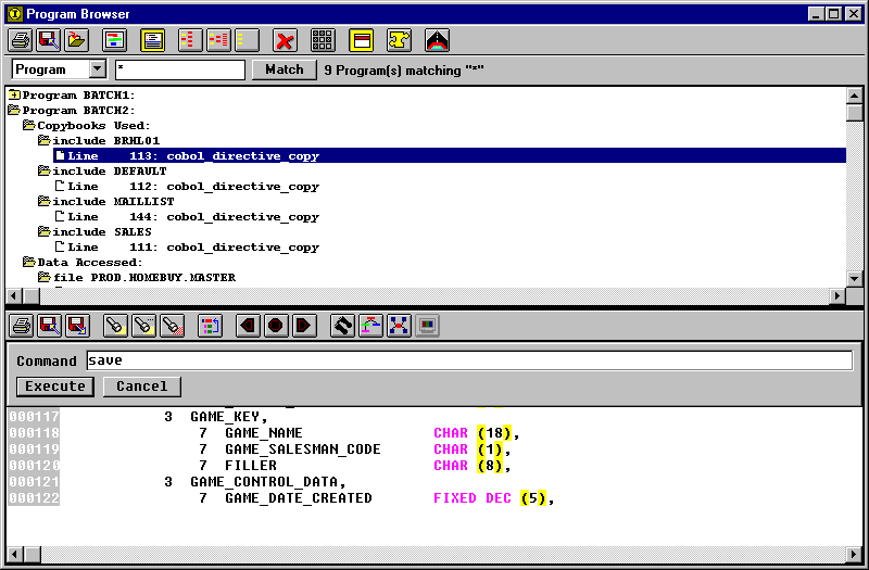
The standard Revolve button bar allows you to perform:
| Function:
|
Button(s):
|
|---|---|
|
Printing: |
|
|
Saving and Loading: |
|
|
Search/Replaces |
|
|
Code Navigation |
|
|
Invoke Views |
|
The Home key on your keyboard invokes a command line where commands can be entered and initiated. For information about different SPF commands and functionality, access the on-line help by typing Help in the command line and hit Return.
When you save a file in the SPF Editor, by clicking
 or typing SAVE in the command line, a
backup of the file prior to your changes is saved as well as the newly
modified version. To distinguish the two versions the editor attaches .BAK
to the end of the original filename and extension. For example, if you make
changes to ONLINE1.CBL and save, there will be a file ONLINE1.CBL.BAK in the
directory. This file is the backup file and contains the data contained in
ONLINE1.CBL before you made changes.
Revolve Views operate in conjunction with Revolve Tools and Browsers to provide an effective and graphical way to analyze complete applications. The Views accessible with Revolve are:
The System view provides a graphical depiction of the relationships between entities (JCL jobs, COBOL programs, data files, etc.) in a project. In addition to the graphical icons, detailed information about each relationship is also provided.
Revolve uses the default options found under the Utilities/Options/Tools/System
menu when opening a System view. Once a System view has
been opened the options can only be modified through the System View
Options dialog, invoked with the Options button
 on the button bar.
For a description of the icons used in the System view choose the Print button from the System view button bar. Then select the Legend check box. Your hard copy will be preceded by descriptions of the icons used in the view.
By default icons are shaded gray but clear icons may also appear. Clear or unshaded icons indicate that an element has duplicate icons in the graph. There will be only one shaded icon for each element in the source code. It is this icon which will be expanded to other elements. Icons which appear segmented symbolize a program entry point.
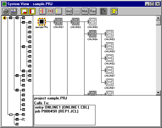
The buttons on the System View button bar provide the following functionality:
| Click This:
|
To Do This:
|
|---|---|
|
|
Opens the Print dialog. The contents of the view can be printed. |
|
|
Invokes the Split Screen Editor. |
|
|
Opens a detail window at the bottom of the System view. Displays specific statements that link items. |
|
|
Opens an overview window that maps the entire system and denotes the current selection as well as any highlighted items. |
|
|
Expands the parent level folder to the first leaf or child folder. |
|
|
Expands the contents of the selected folder. |
|
|
Collapses the selected folder to its unopened appearance. |
|
|
Opens a Find dialog which is used to automatically locate desired items in the System view. |
|
|
Establishes the selected item as the root of the System view. |
|
|
Marks the selected item with an "X." The mark is also displayed in the Overview Window for quick identification. |
|
|
Resets the System view to the original root. |
|
|
Opens the System View Options dialog. |
|
|
Opens a Choose dialog where subprojects can be selected and loaded into the System view. |
Note: It is recommended that the Complete Project dialog box be used to provide Revolve with any missing information before the System view is opened. Refer to Complete Project.
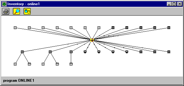
The Inventory view creates a complete graphical view of a program or JOB, including all of their related entities.
Note: It is recommended that the Complete Project dialog box be used to provide Revolve with any missing information before the Inventory view is opened. Refer to Complete Project.
The Duplicates button  ,
unique to the Inventory view, shows more than one icon per entity
when appropriate. The Overview Panel button
  displays the entire view while denoting selected and highlighted items. The
standard Print button displays a Print dialog. For a
description of the icons used in the Inventory view select the Legend
check box from the Print dialog. Your hard copy will be preceded
with descriptions of the icons used in the view.
When the Inventory view is invoked from the Tools menu, an Open Inventory dialog appears. To find a specific program, enter the program name into the Match Edit Box and click the Match button. Or use the scroll-able list to find and select multiple programs for display in the Inventory view. The Select All button selects all of the items in the scrollable list and opens Inventory views for each program.
The Inventory for COBOL programs shows the main program, copybooks/includes, files, databases, screens, programs called, and entities invoking the main program.
The JCL/ECL inventory represents the job/run, steps, devices/files, executables, and DD statements.
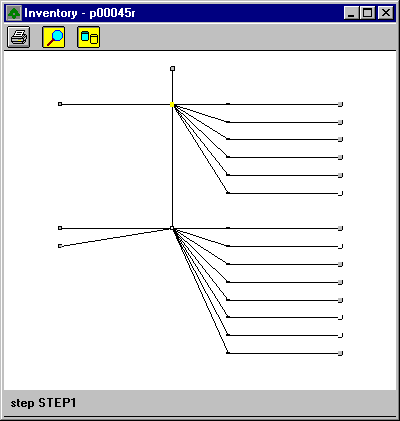
Depending on the DISP parameter of a DD statement, Revolve will place an
arrow inside the DD icon  indicating the usage of the
data set. The following translations are used:
| Parameter:
|
Translation:
|
|---|---|
|
NEW |
write only |
|
MOD |
read/write |
|
OLD |
read only |
|
SHR |
read only |
The Code Flow view displays a flow chart that illustrates the calling hierarchy of the paragraphs and sections in a COBOL program or entry point. The flow chart shows GO TO statements, PERFORM statements, CICS error handlers and fall throughs in relation to the paragraphs and sections in the program.
When the Code Flow view is invoked from the Tools menu, an Open Code Flow dialog appears. To find a specific program, enter the program name into the Match Edit Box and click the Match button. Or use the scroll-able list to find and select multiple programs for display in the Code Flow view. The Select All button selects all of the items in the scroll-able list and opens Code Flow views for each program.
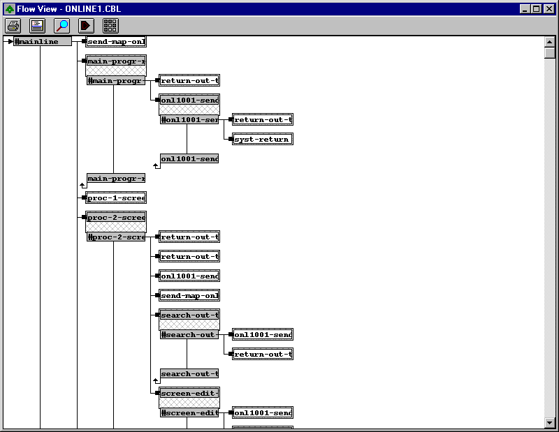
Revolve uses the default options found under the Utilities/Options/Views/Code
Flow menu when opening a Code Flow view. Once a Code Flow
view has been opened, the options can be changed from the Code Flow
Options dialog, invoked by pressing the Options button
 . The Overview Panel button
 opens and closes the Overview
Panel, which maps the current view while displaying currently selected
and highlighted items in the program. If there are multiple occurrences of
the selected component in the program, the Next Usage button
 will be enabled. When
clicked, it will display the next usage.
Some COBOL programs allow execution to fall through the end of a paragraph into a new block of code. This will often result in flow charts that while accurate do not reflect the implied structure of the program. When the analysis is done to create the flow chart, the user can limit the number of times the system can fall through paragraphs that are also used to end a block of code. These paragraphs are referred to as "live" fall throughs because they are designated as exit paragraphs but under certain conditions they may fall through instead of returning. By limiting the number of "live" fall throughs with the Number of Live Fall Throughs option, the user can create a logical representation of the COBOL program.
Code Flow Options allow the user to allocate the number of characters displayed in each label. This allows for customization of the display. The number of characters cannot be set to less than than five.
The Display Error/Exception Branches checkbox allows the user to show or hide branches or exceptions that occur in a program (i.e. CICS handlers or ON ERROR clauses).
The Code Flow Options dialog allows the user to set the number of live fall throughs in a system, to allocate the number of characters displayed in each label, and to specify the display of error/exception branches that occur.
Revolve expects there to be at least one section per COBOL program and one paragraph per section. If these are not explicitly labeled, then they are implied in the database. Programs that do not start with a section label or sections that do not start with a paragraph label appear in the flow charts with names that begin with a "#". For implied paragraphs, the names are derived by taking the name of the section containing the implied paragraph and prefixing it with a "#" character. For implied sections, the name is formed by prefixing the name of the program with a "#" character.
The Code Flow view is a graphical way to view the components of a COBOL program. Interpretation can be difficult unless you understand the significance of the symbols used to create the code flow view.
The Source view creates a logical view showing all the integrated files that comprise a module. For a COBOL program, the copybooks and include files are interleaved in the main source file. For JCL, a logical view that integrates all the proclibs with the main job is shown. The Source view displays the source code as it would appear in its source file format. The overview window runs along the right side of the view and provides a representation of the source file. The selected item's location appears as a horizontal bar in the overview window. Highlighted items will also be displayed in their appropriate color in the overview window.
When the Source view is invoked from the Tools menu, an Open Source dialog appears. To find a specific source file, enter the file name into the Match Edit Box and click the Match button. Or use the scroll-able list to find and select multiple files for display in the Source view. The Select All button selects all of the items in the scroll-able list and opens Source views for each file.

The Source view button bar provides the following functionality:
| Click This:
|
To Do This:
|
|---|---|
|
|
Opens the Print dialog. The contents of the view can be printed. |
|
|
Opens a Save As dialog. |
|
|
Opens an overview window that maps the entire system and denotes the current selection as well as any highlighted items. |
|
|
Invokes the Split Screen Editor. |
|
|
Opens the Search dialog where text strings can be specified and located in the source code. |
|
|
Repeats the last search that was performed. |
|
|
Copies the selection to the clipboard. |
|
|
Returns one logical level in the source code. |
|
|
Undoes the last operation that resulted with the selected line in the source code. |
|
|
Allows the user to view the definition of a variable, paragraph, etc. |
|
|
Selects the next usage of the item. |
|
|
Selects the previous usage of the item. |
|
|
Displays a Highlight dialog which allows you to highlight divisions, copybooks, and comments in the specified color, displayed at the bottom of the Revolve desktop. |
|
|
Invokes the Execution Simulator button bar. The Run/Stop button begins the execution simulation. |
|
|
Initiates the Micro Focus Animator. |
The Data Structure view illustrates the data hierarchy by displaying all the variables in a program, section, or group level.
When the Data Structure view is invoked from the Tools menu, an Open Data Structure dialog appears. To find a specific file, enter the file name into the Match Edit Box and click the Match button. Or use the scroll-able list to find and select multiple files for display in the Data Structure view. The Select All button selects all of the items in the scroll-able list and opens Data Structure views for each file.

The buttons on the Data Structure view button bar provide the following functionality:
| Click This:
|
To Do This:
|
|---|---|
|
|
Opens the Print dialog. The contents of the view can be printed. |
|
|
Opens a Save As dialog where current information can be saved to a text (.TXT) file. |
|
|
Displays an Add To Annotation dialog where selected information can be added to an existing or new annotation. |
|
|
Invokes the Split Screen Editor. |
|
|
Expands the parent level folder to the first leaf or child folder. |
|
|
Expands the contents of the selected folder. |
|
|
Collapses the selected folder to its unopened appearance. |
|
|
Removes the selected item(s) from the Data Structure view. |
|
|
Displays the level, size, and offset of the items. |
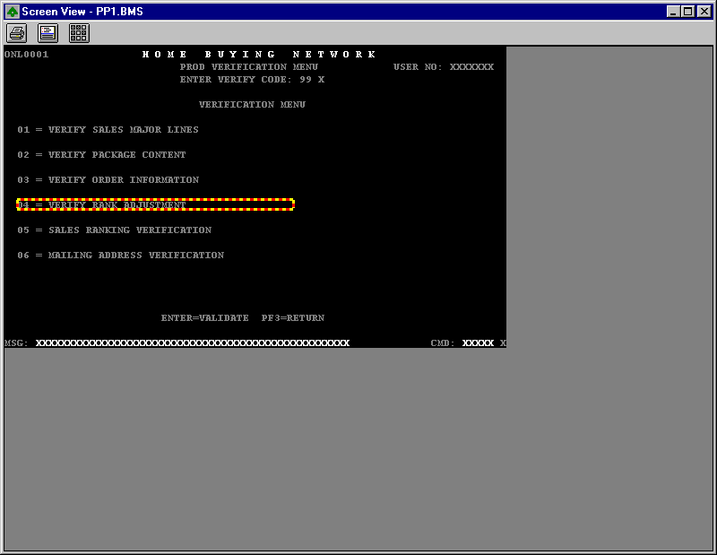
The Screen view creates an image of the BMS or MFS screen as it would be displayed in a production system. Uninitialized fields are shown with "X"s, or "9"s if numeric.
When the Screen view is invoked from the Tools menu, an Open Screen dialog appears. To find a specific BMS or MFS file, enter the file name into the Match Edit Box and click the Match button. Or use the scroll-able list to find and select multiple files for display in the Screen view. The Select All button selects all of the items in the scroll-able list and opens Screen views for each file.
Copyright © 1998 Micro Focus Limited. All rights reserved.
This document and the proprietary marks and names
used herein are protected by international law.
 | Setting Up Projects | Information Browsers |  |