C.3 Preparing the Target VMware Environment

Before you begin the semi-automated (X2P) migration of a Windows Server Failover Cluster to VMware VMs with RDM disks, you must prepare your target VMware environment. See Table C-2, Configuration Requirements for Target VMware Components.

NOTE:Perform the following tasks in the order presented.

C.3.1 Create LUNs on the SAN

For each shared quorum or data disk on the source Windows cluster, create a LUN (logical disk) on the appropriate SAN connected to your VMware environment. Ensure that each LUN size is large enough to fit the source shared disk to be migrated.

For information about creating LUNs, refer to your SAN vendor documentation.

Continue with Create the Heartbeat Network.

C.3.2 Create the Heartbeat Network

The VM nodes for the Windows cluster need a heartbeat network in the VMware environment to communicate a heartbeat with one another. Ensure that the second NIC on each target VM belongs to the heartbeat network.

This section provides basic instructions for two possible methods for creating a heartbeat network in your VMware environment. Refer to VMware documentation for other possible solutions.

Creating a Heartbeat Network Using vSphere Standard Switches

To create a heartbeat network, you can configure vSphere Standard Switches (vSS) identically on each host and add a virtual machine port group for the heartbeat network on each switch. Each host contributes an available NIC to use as the uplink, which is required for communications between nodes across the hosts. You configure the second NIC on each VM to use the heartbeat network.

Figure C-2 Target VM Environment Using vSphere Standard Switches

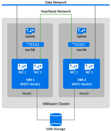
If you have other VMware hosts that you want the VMs to be able to fail over to using VMware HA in a VMware cluster, you must add the switch and port group to that host as well, using identical vss switch and VM port group names.

NOTE:For detailed information about how to create standards switches and port groups and configure adapters to use them, see the following articles on the VMware Documentation website:

To create the heartbeat network using standard switches:

  1. Create a vSphere Standard Switch on the VMware host where you will create a target VM for the Windows cluster.

    1. In the vSphere Web Client navigator, view Hosts and Clusters, then select the host.

    2. On the Configure tab, expand Networking, then select Virtual Switches.

    3. Under Virtual Switches, click the Add icon to add a new switch.

    4. In the Add Networking wizard, proceed through the wizard to configure a new vSwitch.

      Add Networking Wizard Page

      Description

      Connection type

      Select Virtual Machine Port Group for a Standard Switch, then click Next.

      Target device

      Select New Standard Switch, then click Next.

      Create a standard switch

      Specify the host adapter to use for the heartbeat communications across hosts for the Windows cluster VMs, then click Next.

      This creates an uplink that allows communications between the cluster VM nodes on different hosts.

      Connection settings

      Specify a label for the network, such as vss-hb.

      Ensure that you use the same label for this network on all host nodes that you will use with the planned VM nodes for the Windows cluster.

      Ready to complete

      Review the configuration, then click Finish.

  2. Create a Virtual Machine Port Group for the newly created vSwitch.

    1. In the vSphere Web Client navigator, view Hosts and Clusters, then select the host.

    2. Select the Manage tab > Networking tab, then select Virtual Switches.

    3. Under Virtual Switches, click the Add icon to add a port group to the newly created vSwitch.

    4. In the Add Networking wizard, proceed through the wizard to configure a new port group for the heartbeat network.

      Add Networking Wizard Page

      Description

      Connection type

      Select Virtual Machine Port Group for a Standard Switch, then click Next.

      Target device

      Select the Select an existing standard switch radio button, click browse, select the vss-hb vSwitch you created and click OK, then click Next.

      Connection settings

      Specify a label for the network, such as heartbeat.

      Ensure that you use the same name on all host nodes that you will use with the planned VM nodes for the Windows cluster.

      Ready to complete

      Review the configuration, then click Finish.

  3. In Network view, expand the location where the host resides. You'll see an entry for the vss-hb switch, the uplink container for the switch, and the virtual machine port group (heartbeat).

  4. Repeat these steps for the second host to create a standard switch and virtual machine port group with the identical names.

  5. Continue with Create Target VMs on Different Hosts in a VMware Cluster.

Creating a Heartbeat Network Using vSphere Distributed Switch

To create a heartbeat network, you can alternatively configure a vSphere Distributed Switch on the VMware Cluster and add a virtual machine port group for the heartbeat network on the distributed switch. You add the hosts to the heartbeat port group. This configuration makes it easy to manage the network settings and heartbeat port group across all the hosts you want to include. Hidden vSS switches are automatically created on the member hosts. Each host contributes an available NIC to use as the uplink, which is required for communications between nodes across the hosts. You configure the second NIC on each VM to use the heartbeat network.

Figure C-3 Target VM Environment with a vSphere Distributed Switch on the Cluster

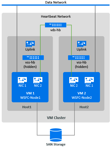
If you have other VMware hosts that you want the VMs to fail over to using VMware HA in a VMware cluster, you must add the host to the vSphere Distributed Switch and port group.

NOTE:For detailed information about how to create distributed switches and port groups and configure the VMs to use them, see the following articles on the VMware Documentation website:

To create the heartbeat network using standard switches:

  1. Create a vSphere Distributed Switch on the VMware cluster where you will create a target VM for the Windows cluster.

    1. In the vSphere Web Client navigator, view Hosts and Clusters.

    2. Right-click the VMware cluster, then select Distributed Switch > New Distributed Switch.

    3. In the New Distributed Switch wizard, proceed through the wizard to configure a new distributed switch.

      New Distributed Switch Wizard Page

      Description

      Name and Location

      1. Specify a name for the switch, such as vds-hb.

      2. Specify the location of the parent cluster you selected.

      3. Click Next.

      Version

      Specify a VDS Version that you want to use, such as Distributed Switch 6.5.0, then click Next.

      Choose the most recent version available that is compatible with the ESXi version running on the VMware cluster's member hosts.

      Edit Settings

      1. Number of uplink ports: 1

        Each member host must have one available physical adapter associated with the uplink. You will add the hosts and select the adapters that each will use later.

      2. Network I/O control: Enabled

      3. Default port group: Select Create a default port group setting.

      4. Port group name: heartbeat

      5. Click Next.

      Ready to complete

      1. Select Automatically create a default port group.

      2. Review the configuration.

      3. Click Finish.

  2. In Network view, expand the location where the cluster resides. You'll see an entry for the vds-hb switch, the uplink container for the switch, and the distributed virtual port group (heartbeat).

  3. Add hosts to the vds-hb switch.

    1. In the Network view, right-click the vds-hb switch, select Add and Manage Hosts, then proceed through the wizard.

      Add and Manage Hosts Wizard Page

      Description

      Task

      Select Add Hosts, then click Next.

      Hosts

      1. Click the New Hosts (+) icon, then select the hosts (HOST1 and HOST2) to add to this switch.

      2. At the bottom of the page, deselect Configure identical network settings on multiple hosts (template mode).

        With this option, you will be able to specify which of the available adapters to use on each host. Adapter numbers for the uplink can be different on each host.

      3. Click Next.

      Network adapter tasks

      1. Select Manage physical adapters.

      2. Deselect any other adapter tasks that might be selected.

      3. Click Next.

      Physical network adapters

      For each host for the target VMs, select an available physical adapter to use for the uplink, then click Next.

      Analyze impact

      The configuration on each host should have a status of No Impact.

      Ready to complete

      Review the configuration, then click Finish.

  4. In the vSphere Web Client navigator, select the vds-hb switch, then click the Hosts tab. You’ll see list of the member hosts for the port group.

  5. Continue with Create Target VMs on Different Hosts in a VMware Cluster.

C.3.3 Create Target VMs on Different Hosts in a VMware Cluster

Create two new target VMs (VM1 and VM2) for migrating the source active/passive nodes of the Windows cluster. Create each VM on a different host nodes in the same VMware cluster. That is, you will create VM1 on Host1 and create VM2 on Host2.

NOTE:For detailed information about creating a virtual machine, see Create a Virtual Machine with the New Virtual Machine Wizard on the VMware Documentation website.

To create target VMs on your VMware hosts:

  1. Log in to the vSphere Web Client.

  2. Launch the Host and Clusters view to display the inventory objects in the client.

  3. Under the appropriate VMware cluster, right-click the VMware host node (Host1 or Host2) where you want to create the target VM (VM1 or VM2) and select New Virtual Machine.

  4. In the New Virtual Machine wizard, select Create a new virtual machine, then proceed through the wizard to create the virtual machine.

    The following procedure describes options for the New Machine Wizard in VMware 6.7. Apply the recommended configuration settings according to the wizard version you use.

    New Virtual Machine Wizard Page

    Description

    Creation type

    Select Create a new virtual machine, then click Next.

    Name and folder

    1. Specify a name for the virtual machine that is unique among the VMs that will run in the VMware cluster.

    2. Specify the VM folder where you want to create the virtual machine files.

    3. Click Next.

    Compute resource

    Select the resource pool for the VM, then click Next.

    Storage

    Select a datastore where you want to store the virtual machine configuration file and the virtual machine disk (.vmdk) file, then click Next.

    Compatibility

    Specify the VM compatibility with the ESXi host version that is required for the Windows OS you are migrating, then click Next.

    Guest operating system

    This setting must match the OS that will eventually be running on the target VM after migration.

    1. Guest OS family: Select the Windows operating system.

    2. Guest OS version: Select the Windows OS version that matches the source cluster node.

    3. Click Next.

    Customize hardware

    Configure the VM hardware and options, then click Next. Ensure you configure the following settings:

    • CPUs: As required

    • Memory: As required

    • Network: Add two NICs.

      • NIC1: data network, connect at power on

      • NIC2: heartbeat network, connect at power on

    • SCSI controller: Select LSI Logic SAS, which will be used for the eventual Windows OS after migration on cutover.

    • Virtual disk: Create a new disk with a size that matches the source OS disk. Ensure that you use Thick Provision Eager Zeroed format for this system disk.

    • Virtual CD/DVD: Point to the PlateSpin ISO Image File (bootofx.x2p.iso) that you downloaded on your local machine.

    • Boot firmware: Specify the boot firmware (EFI or BIOS) on the target VM to match the boot firmware on the source cluster node.

    Ready to complete

    Review your configuration selections, then click Finish to create the virtual machine.

    NOTE:Do not add shared cluster disks at this time.

  5. Repeat Step 3 to Step 4 to create the second target VM (VM2) on a different host node (Host2) in the same VMware cluster.

  6. Continue with Section C.3.4, Create RDM Disks on Target Virtual Nodes.

C.3.4 Create RDM Disks on Target Virtual Nodes

In VMware, you can use raw device mapping (RDM) to store shared data directly on a LUN in your SAN, instead of storing it in a virtual disk file. After you configure the heartbeat network for the target Windows cluster nodes, you are ready to add RDM disks to the target VM nodes.

NOTE:For detailed information about working with RDM disks, see Add an RDM Disk to a Virtual Machine on the VMware Documentation website.

On the Virtual Target VM1

To configure RDM disks on VM1:

  1. Log in to the vSphere Web Client.

  2. Launch the Host and Clusters view to display the inventory objects in the client.

  3. Right-click VM1 and select Edit Settings, then configure a SCSI controller for the shared disks to use on the VM1 node:

    New Device Option

    Description

    SCSI Controller

    1. In the Virtual Hardware tab, select SCSI Controller, then click Add.

    2. SCSI Bus Sharing: Physical

    3. Type: LSI Logic SAS

    4. Click OK to create the new SCSI controller.

    This SCSI Controller should be used for every shared RDM disk that you create on VM1.

  4. Right-click VM1 and select Edit Settings, then create and configure a shared RDM disk that will be available to all VM nodes for the Windows cluster:

    New Device Option

    Description

    RDM Disk

    1. In the Virtual Hardware tab, select RDM Disk, then click Add.

    2. Select the LUN you created for a shared RDM disk. For example, select the LUN for Quorum Disk.

    3. Click OK to create the new RDM Disk.

    Properties for the new RDM disk

    1. Specify where to store the mappings file. By default the Store with Virtual Machine option is selected.

    2. Ensure that Compatibility Mode is set to Physical.

    3. Ensure that Sharing is set to Unspecified.

    4. Click OK.

  5. In the properties of the new RDM disk, set Virtual device node to SCSI Controller 1 (the newly created controller from Step 3).

  6. Repeat Step 4 and Step 5 to add an RDM disk for each LUN you created for the target Windows cluster.

  7. Continue with On Virtual Target VM2.

On Virtual Target VM2

To assign the shared RDM disks on Target VM2: 

  1. Log in to the vSphere Web Client.

  2. Launch the Host and Clusters view to display the inventory objects in the client.

  3. Right-click VM2 and select Edit Settings, then configure a SCSI controller for the shared disks to use on the VM2 node:

    New Device Option

    Description

    SCSI Controller

    1. In the Virtual Hardware tab, select SCSI Controller, then click Add.

    2. SCSI Bus Sharing: Physical

    3. Type: LSI Logic SAS

    4. Click OK to create the new SCSI controller.

    This SCSI Controller should be used for every shared RDM disk that you create on VM2.

  4. Right-click VM2 and select Edit Settings, then create an RDM disk in the same order that you created them for VM1.

    New Device Option

    Description

    Existing Hard Disk

    1. In the Virtual Hardware tab, select Existing Hard Disk, then click Add.

    2. Browse and select the LUN that you created for the corresponding RDM disk on VM1.

    3. Click OK to create the new RDM disk on VM2.

  5. In the properties of the new RDM disk, set Virtual device node to SCSI Controller 1 (the newly created controller from Step 3).

  6. Repeat Step 4 and Step 5 to add an RDM disk for each shared RDM Disk you created on VM1 for the target Windows cluster.

  7. Continue with Section C.3.5, Configure VM NICs for the Heartbeat and Data Networks.

C.3.5 Configure VM NICs for the Heartbeat and Data Networks

When you created VMs in the New Virtual Machine Wizard, you created two NICs for each VM and configured the following settings:

  • NIC1: data network, connect at power on

  • NIC2: heartbeat network, connect at power on

NOTE:For detailed information about configuring and managing NICs for the VM, see Change the Virtual Machine Network Adapter Configuration.

Use the following instructions if you need to reconfigure the NICs after you create the VMs. Ensure that the NICs are configured identically on the target VM nodes.

To configure network settings for NICs on the target VM nodes:

  1. Configure NIC1 on the target VM node to use the data network.

    1. In the vSphere Web Client navigator, right-click the VM node (VM1 or VM2) and select Edit Settings.

    2. On the Virtual Hardware tab, expand Network adapter, and select the data network as the Network for NIC1.

    3. Ensure that the Status is set to Connect at power on.

    4. Click OK.

  2. Configure NIC2 on the target VM node to use the heartbeat network.

    1. In the vSphere Web Client navigator, right-click the VM (VM1 or VM2) and select Edit Settings.

    2. On the Virtual Hardware tab, expand Network adapter, and select the heartbeat port group as the Network for NIC2.

    3. Ensure that the Status is set to Connect at power on.

    4. Click OK.

  3. Repeat these steps to configure NIC1 and NIC2 identically on the second VM node (VM2).